RJ45 Wiring Diagrams: T568A vs. T568B Explained
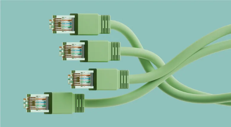
Two accepted wiring standards exist for terminating RJ45 connectors, and most confusion in the field comes down to a single question: not which one is correct, but which one is being used consistently across a given run. Both standards perform identically. The difference that actually matters is knowing which standard governs a project and reading a wiring diagram correctly enough to confirm it.
What an RJ45 Wiring Diagram Shows
An RJ45 connector has eight pins, and each pin carries one wire from a twisted-pair cable. Standard Cat5e, Cat6, and Cat6A cables contain four twisted pairs: orange, green, blue, and brown, each paired with a white-striped conductor of the same color. Holding the connector with the clip facing away and the contacts facing up, the pins are numbered one through eight from left to right. A wiring diagram maps each of those eight color-coded wires to its correct pin position.
That mapping isn't arbitrary. Pin and pair order is standardized specifically to control crosstalk between pairs and preserve signal integrity, and to keep terminations consistent across manufacturers and job sites. Two different technicians, working from two different supply houses, should be able to terminate the same cable to the same result if they're both reading the same standard.
T568A vs. T568B: The Two Wiring Standards
The two recognized standards are T568A and T568B. The distinction between their wiring color codes comes down to the placement of two pairs.
Pin | T568A | T568B |
1 | White/Green | White/Orange |
2 | Green | Orange |
3 | White/Orange | White/Green |
4 | Blue | Blue |
5 | White/Blue | White/Blue |
6 | Orange | Green |
7 | White/Brown | White/Brown |
8 | Brown | Brown |
Blue and brown pairs sit in the same positions under both standards. The only difference is that the green and orange pairs swap places. Neither standard delivers better performance than the other; a link wired correctly to either one transmits data at full spec. What matters is consistency: both ends of a cable, and ideally an entire project, should follow the same standard so pin assignments line up correctly at every termination point.
T568B is the more common standard in commercial and enterprise network builds across North America, a pattern that traces back to its earlier adoption in telephone wiring conventions. T568A shows up more often in older infrastructure, government specifications, and some international deployments. Neither is a default that should be assumed; the correct standard for a given project is whatever that project has already established.
Straight-Through vs. Crossover Wiring
A straight-through cable uses the same wiring standard on both ends and is the wiring configuration nearly all modern commercial network builds rely on, connecting devices such as a workstation to a switch or a switch to a patch panel. A crossover cable uses T568A on one end and T568B on the other, historically used to connect two similar devices directly to each other without an intermediate switch.
Crossover wiring is worth knowing as reference context, but it has become largely unnecessary in current network design. Most modern switches, routers, and network interface cards include Auto-MDI/MDIX detection, which automatically senses and corrects for wiring configuration regardless of which standard is present at either end. For nearly all present-day commercial network cabling, straight-through wiring on a single consistent standard is the expectation.
Why Category Rating and Shielding Affect Pin/Pair Performance
The T568A/T568B pin assignment itself doesn't change based on cable category, but the stakes attached to getting it right increase as category rating climbs. Cat5e cabling operates at lower frequencies with more tolerance for minor inconsistencies. Cat6 and especially Cat6A push into higher frequency ranges where alien crosstalk and return loss become tighter constraints, and where a wiring error is more likely to produce a measurable performance problem rather than a cable that simply fails outright.
Shielded (STP) construction versus unshielded (UTP) construction doesn't alter the wiring standard either, but shielding and proper grounding become more relevant to overall link performance as category rating and electromagnetic interference exposure both increase. A Cat6A shielded run in a high-EMI environment, such as a large equipment rack or a space near heavy electrical infrastructure, has less margin for termination inconsistency than a Cat5e unshielded run in a low-interference space.
Matching RJ45 Connectors to Cable Category and Shielding
Once the wiring standard and category are established, the connector itself needs to match both the cable's category rating and its shielding requirement. Unshielded connectors are appropriate for standard Cat6 runs in controlled electromagnetic environments. Shielded connectors, available with internal or external ground configurations, support Cat5e and Cat6 Ethernet cable wiring families where EMI exposure calls for additional protection. For Cat6A runs supporting 10 Gigabit applications, shielded connectors built with internal liners help maintain pair alignment and reduce return loss at the higher frequencies those links operate at.
Matching connector to cable category and shielding type is a straightforward reference task once both variables are known, and it's a decision made before termination begins rather than during it.
Sourcing Cat5e, Cat6, and Cat6A RJ45 Connectors
We supply RJ45 connectors across Cat5e, Cat6, and Cat6A, in both shielded and unshielded configurations, engineered to pair with WCW's low-voltage cable families. For teams speccing a full structured cabling run, the Pro AV cable resource center outlines cable options by category and application, and our team is available to help match connector, cable, and shielding requirements to a project's specifications.
